Generally
large number of users log into SAP sytem. The dialog work processes
(wp) available to the users are limited due to performance & system
limits. The objective of a dialog work process is to handle the user
requests quickly and display the results. Dialog work process also takes
large resources relatively to background processes for display
purposes. So it is not wise to have a dialog work process running for
each user logged in. A dialog work process is not assigned to a single
user for longer time. When a dialog user fires a request, the dispatcher
assigns a dialog WP to handle the request. When the request is
processed, it relieves the work process from that user so that other
users can use it. This helps in handling requests from a large no of
users with small no of dialog work process and optimum use of resources.
Monday, October 6, 2014
Saturday, October 4, 2014
How to Kill a work process in SAP
Description
You
may see a work process in SAP in hung state thru SM50 transaction code. The following steps will explain you the
detailed process on dealing with the killing it.
Procedure:
1. Try
to kill it in SM50. Select the work
process, and in the Process menu, select either Kill with core, or without core
option.

2. Use
transaction SM04 using the Sessions
button. Try to end all the sessions of the user.

3. If
killing the process via the SAP instance fails, you will need to kill it from
the Operating system level. Identify the PID of the work processes enter a kill -9 from a Unix command prompt.
Incase
of Windows, you can do it from Windows Task manager.
4. On
NT, if everything else has failed, there should be an executable called sapntkill in your \usr\sap\\SYS\exe\run directory. Use the PID with it.
You
can also use the RSBDCOS0 program,
incase if the issue is not resolved.
However,
the most important thing to remember when killing a WP in SM50 is Change to restart option to No as otherwise the session can
jump back in sometimes as most of its memory is not actually living in the WP.
Allow
5-10 minutes of time to stop, there is no need to do it many times.
http://www.saptechies.com/how-to-kill-a-work-process-in-sap/
http://www.saptechies.com/how-to-kill-a-work-process-in-sap/
Dialog work process Multiplexing
Friday, October 3, 2014
SAP BASIS NOTES -5
Starting and Stopping of SAP:-
When we start SAP the following sequence is executed
Database
Central instance
Dialog Instance or any other Instance <Optional>
The starting and stopping from windows can be done using SAP Microsoft Management Console. In MMC right click on <SID> will give the following options
Start
Stop
View Start Profile
View Instance Profile
Trace
The color-coding for the status of the sap server
Yellow
Green
Red
These colours are Vise-versa in Start & Stop
Three types of profiles
Start/Stop of SAP systems at the background is controlled by set of profiles which are located at
\USR\SAP\DEV\SYS\Profile where DEV is the SYSID
1) Default Profile DEFAULT.PFL
2) Start Profile START_DEVBGMS01_<HOSTNAME>
Where 01 is the instance number
3) Instance Profile <SYSID>_DEVBGMS01_<HOSTNAME>
Where 01 is the instance number
-> Never edit the startup profile because this profile is related with starting/stopping of SAP system.
-> First profile which is read while staring SAP system is start profile and is followed by instance profile.
-> All work processes are configured in instance profile. This profile is specific to the instance in which the
SAP is installed. Any changes made to the startup profile will affect only that particular instance.
-> All changes made to default profile will affect the entire instances, which are configured.
Contents of Startup Profile:
SAPSYSTEMNAME
INSTANCENAME
SAPSYSTEM
SAPGLOBALHOST
Startdbs.cmd -> DB
Msg_server.exe -> Central Instance
Disp+work.exe -> Dispatcher
Igswd.exe -> Java
Start/Stop in Unix:
Commands used to start and stop at OS level in Unix environment.
StartSAP
StopSAP <DB>
<R3>
<ALL>
Directory Structure:The directory structure for SAP installed files will be
\USR\SAP\<SYS_ID>\
PRFDOG
TMP
TRANS
What are the steps involved in stopping SAP system?
Before stopping SAP system we need to check the status of the following
• Check if there are any logged on users. Use Transaction Code – SM04
• Check if there are any Background process is to define – SM36
• Check if there are any Background processing is going on. Use TC – SM37
• Check if there is any Batch input session. Use TC – SM35
• Check if there are any update processes running. Use TC – SM13
Note:
1) After verifying the above status we need to send a message to all the users stating the shutdown time using Transaction Code SM02.
2) All transaction codes that we monitor are executed in the central Instance only.
3) To view the users who are logged into all the instances we can use Transaction code AL08 (Global
User Overview)
4) Transaction code to view profile parameters RZ11.
5) Trans Code to edit or change the profile parameters is RZ10.
6) Report “RSPFPAR” is used to provide the same functionality as RZ11.
Sap system profiles :-
There are two types of of profile parameters
1) Static Parameters
2) Dynamic Switchable
For dynamically switchable parameters, we need not restart the SAP system after making the changes. For static parameters, we need to restart the SAP system to make the changes effective.
In the table “TPFYPROPTY”, the dynamic indicator (X) identifies all dynamic switchable profile parameters.
Note:
• Use Transaction code SE16 to view the contents of a table.
• To display profile parameters from OS level we need to use the following
Sappfpar <Parameter Name>
<ALL>
<Check>
<Help>
Eg: sappfpar ALL will return the list of all parameters.
Modes of Editing Profile:-
There are 3 types of edit profiles
1) Administration of Data
2) Basic Maintenance
3) Extended Maintenance
1) Administration of Data: contains type of profile, short description, path of profile, Name of instance and the time of last activation. This profile mode is used only to display the profile parameters.
• You can perform the maintenance of parameters using either basic maintenance or extended.
2) Basic Maintenance: allows adjusting most important parameters and provides logical description.
3) Extended maintenance: display the unformatted content of the profile i.e. technical names of the profile.
• In extended maintenance we can change the values, add values as well as delete.
• Changes are done in 2 steps.
Copy == Changes are temporarily copied
Save == Changes are permanent saved to database
• Changes to instance specific profiles takes effect only after a restart of the corresponding instance.
• Profile parameter related to security administration starts with auth* in RZ10
• Profile parameter related to work processes starts with rdisp* in RZ10
Steps for tuning Work Processes
• In the command prompt of SAP Execute RZ10.
• In the new screen opened to edit the profile parameters, choose Utilities option from the Menu
1) Inside Utilities choose the option Import Profile of Active Servers. This step is used to read 3 profile parameters from OS level to SAP level. Output of these steps is that it displays profile check log. In which it will show status of the three profiles i.e. any errors in reading the profiles.
2) Press back button
3) Select profile tab and select instance profile.
4) Goto extended maintenance and select [Change] button
Note: To create a new parameter select [Create Parameter] button.
To change the value of the existing parameter, select the parameter under the parameter name column and click on change button.
• Change the value and select [Copy] button
• Select [Back] and again click on [Copy] button
• Click on [Back] and click on [save] button.
First steps to work with Change Request Management scenario (ECC 6.0 Post Installatio)
With
the following steps you will be able to create a test landscape to
practice with the Charm scenario in Solution Manager 7.0 without
creating interferences with real TMS landscapes.
Also I will try to give tips and tricks for the common mistakes in the configuration of this scenario.
The configurations given are valid for Solution Manager 7.0 since SP9 and above.
Step 1- Create the test landscape
Usually you would like to use Charm to manage the changes in this kind of TMS landscapes:
DEV:100 -->QUA:200 -->PRD:300
The
test landscape that I am proposing is this one: your Solution Manager
is installed in system SMM for example, and you are configuring client
001 for being used as Charm client, them SMM:001 is your Charm client.
Create
three additional clients in SMM, like local client copy from client 000
with SAP_ALL profile (this will need some extra space in SMM system,
but not too much), let say you create clients 100, 200 and 300.
We
assume that SMM:100 is going to be the Development system, SMM:200 the
Quality system and SMM:300 is the Production system.
In SCC4 assign the following client settings, roles, etc. to these clients, this is important!
Customizing role for SMM client 100
Test role for SMM:200
Production role for SMM:300
The indications given for this test case from now on also apply to for your real TMS landscape, to DEV, QUA and PRD system.
Note:
In ChaRM we do support two-system landscape, to use it you should firstly configure the consolidation route in STMS correctly.
Then
set up the development system as type of role "Source System", and
production system as type of role "Production System" in your project
system landscape. In such projects there should be no target system
needed.
Please
always keep in mind that production system is very special in ChaRM so
make sure there is at least one in each of your project.
See
that in two-system landscape no test transport will be generated for
normal correction SDMJ, since officially this functionality is only
designed for test system, see note 1419150 ChaRM: Transport of Copies
(ToC) with two-system landscape.
Step 2- Configuration of TMS for this scenario according to Charm prerequisites
In Solution Manager, in client 000, call STMS (the same must be done in the domain controller system of your real landscape)
Note: SMM client 001 does not need to take part of your TMS landscape.
Select Transport Routes icon:
For
this test landscape initially you have system SMM and none transport
route defined (for a real landscape you will have the three system boxes
DEV, QUA and PRD):
Make
double-click on system SMM and fill the following values (or in the box
of the development system and after in the quality box):
In
System Attributes tab: the use of Single transport is a prerequisite
for Charm for all the systems in the landscape; you will see this in
detail in section Step 3.
In
Standard Transport Layer tab: ensure you enter the client 100, (client
with customizing role for the development box, client with test role for
the quality box).
Create
the consolidation transport routes to SMM:200, transport route must be
CLIENT SPECIFIC for the use in Charm scenario, this is real important!
From development system to quality system you need at least two consolidation routes, SAP and ZXXX.
Go with the pencil from the system SMM to system SMM and get this pop-up:
I
create the consolidation route for transport layer SAP and I do the
same to create transport route for transport layer ZSMM (for customer
developments).
In case of a real landscape you need to choose from which system to which system and client.
I
make the same to create the Delivery transport route from SMM:200 to
SMM:300, delivery routes are always from quality to production systems.
Finally you will get the following situation:
Save and distribute the changes:
All the previous work has to be done in the satellite systems in real landscapes.
Step 3- Review of the main configuration points in SPRO
1. All point under SAP Solution Manager -->Configuration -->Basis Settings must be performed.
Especially important point is:
RFC
connections from Solution Manager to DEV, QUA and PRD system, don’t
forget to create also SM_..._TMW connection to all satellites DEV, QUA
and PRD, to clients with customizing, test and production roles, in our
example, we will create the RFC connection to 100, 200 and 300. Also to
client 000 of all the involved systems, DEV, QUA and PRD systems in our
example.
In transaction SMSY:
Also
you need to create the RFC connections from Solution Manager SMM:001 to
client 000 in the system that is the domain controller of your real
landscape, this is really IMPORTANT!!! You will see more information
about this in spro point “Generate RFC Destinations to Client 000"
Note:
usually the domain controller is always in DEV system as this was the
first system in the landscape to be installed. If you move the domain
controller to PRD system, as it is recommended, don´t forget to create
the RFC connection to client 000 of this domain controller system.
2. In SPRO go to Scenario-Specific Settings-->Change Request Management -->Standard Configuration
General Activities:
2.1. Run “Activate Integration with Change Request Management”
After this check in SM30 that view BCOS_CUST has the following entries:
CHARM W NONE CUST620 1.0
CHARM_DEST W NONE CUST620 1.0
This means that Charm configuration has been done in this client.
2.2. Activate BC Sets: Check note 903527
Bc Set for Charm: SOLMAN40_CHARM_BASICFUNC_001
Under Transport Management System check the following in detail:
2.3. Define Transport Routes for System Landscape: already explain in steps above
2.4 Activate Extended Transport Control: apply this point to all systems in real scenario
2.5 Configure Transport Strategy: apply this point to all systems in real scenario
2.6. Activate TMS Trusted Services: apply this point to all systems in real scenario
2.7. Activate Domain Links: you have to create inter-domain links
If you go to STMS in the solman system you can see that the solman system is in transport domain DOMAIN_SMM for example.
In your real landscape, DEV, QUA and PRD will belong to another transport domain, usually called DOMAIN_DEV.
What
you need to do in this spro point is to make these two transport
domains known each other, I mean as the solman system is going to call
TMS functions in the transport domain of DEV, QUA and PRD, the TMS of
solman must know this other transport domain.
From help.sap.com:
To request a link between two transport domains, proceed as follows:
- Log on to one of the two domain controller systems, in solman system for example.
- Call transaction STMS (always being in client 000).
- Choose Overview --> Systems.
The system overview appears.
- Choose SAP System-->Create --> Domain link.
The dialog box Request for Linking 2 Domains appears.
Enter
system name, DEV for example, hostname where is installed the system
and system number, all this information is in SM51 of this DEV system,
if DEV system is the domain controller of your real landscape.
Your
SAP System performs the following actions automatically:- Generates the
required RFC destinations. - Sends the address data of the controller
to the controller in the other domain.After you have to logon in the
domain controller, client 000, of your real landscape and confirm the
link between these two domains as follows:
- Log on to the domain controller in the other domain.
- Call Transaction STMS in client 000.
- Choose Overview -->Systems. The system overview appears.
-
Position the cursor on the domain controller where you requested the
domain link, DOMAIN_SMM in our example, and choose SAP Systemà Approve.
- Confirm the prompt and distribute the configuration.
The
two domain controllers now exchange all necessary information about the
systems in their domains. This information is distributed to all
systems in the domain whose controller you are currently logged on to. A
transport profile is generated, which contains all systems in both
domains.
You have to see something like this in your solman system (called SSM in this real example):

And this in the DEV system (called ED4 in this real example):
To
check that the domain link is ok go in solman system and in development
system to STMS->transport routes, in the top of the screen you will
see that in solman system the systems belonging to the other transport
domain appear like boxes and the same if you go to STMS in DEV system,
the box of the solman system can be seen.
The
information about the systems in the other domain is not automatically
distributed to the systems in the domain where you requested the domain
link. This means that you must distribute the new configuration to these
systems.
2.8. Generate RFC Destinations to Client 000: already explained.
2.9. Add Import Authorization to Operator/Administrator: According to note 913232
"Therefore,
the TMS requires that the people responsible for the import (operator
or administrators with import authorization) have a user in the client
000 of the target system".
This
means that you need to define these users in the client 000 of all
target systems involved in the landscape with import authorizations.
Under Change Request Management:
2.
10. Set Project Assignment of Requests as Mandatory: not totally
mandatory but this will avoid users creating transport orders directly
in development system. All transport orders in development system in
your real landscape must be created from the solman system via a Change
Request.
2. 11. Maintain Number Ranges: run this.
None of the configuration points under “Extended configuration” are required if you want to use the standard Charm scenario.
Now you are ready to create a project.
Step 4. In Solution Manager go to transaction SOLAR_PROJECT_ADMIN
Please go to http://service.sap.com/rkt-solman
Select
SAP Solution Manager 7.0, select Learning Map for Supp
Organizations/Serv providers, open Change Request Management section and
see the iTutor called:
“Create a Project”
The main points in the creation of a project for Change Request Scenario are:
-
Decide if your project is an implementation or a Maintenance project;
see the differences in the Solution Manager Documentation. For our test
case select a maintenance project.
Systems: here you have to enter your logical component
Take into account that all systems that belongs to the TMS landscape must be assigned to the same logical component, because all system must have the
same product version (exception in case of an upgrade).
This means that in the same logical component each system must have assigned a role, you can have a minimum of two systems for Charm scenario but you can have for example 5 systems with different roles in your real landscape.
In our test case you will have this:

Always
define here the same landscape that you have defined in the STMS of the
real landscape, if not the Charm scenario can not be activated. This
point is always the point that more problems gives in the activation of
Charm scenario!!!
-
In IMG project tab: define always a project in the development system
ONLY! You need to define this project in the development system in
order to assign to this project all transport orders that you are going
to create via a Change request in the solman system, this is a
prerequisite for Charm scenario!
See the above iTutor to see how to define this IMG project.
Don’t define IMG projects in other roles, systems, different to development.
Select Create Task List
Select the name of your Maintenance Cycle also called Project Cycle.
Note: Choose Lock/Unlock Grroup/Subsequent Groups to unlock the tasks in the task list. If all is working correctly a Task List and a Maintenance transaction type SDMN (called Service Desk Transaction in the screenshot) is being created.
Service
Desk Transaction Tab: This tab is not appearing in SP9 but appears in
SP13 and above and shows the SDMN document for this project cycle.
The
task list is one representative of the cycle and represents the system
landscape tracks with tasks to be used by an IT operator for managing
project related IT activities, especially imports.
The SDMN transaction represents the service request for managing the phase changes.
In
SP9 you went to Task List to Activate the maintenance cycle and also to
change the phases of this maintenance cycle, in SP13 and above it are
recommended to go to the maintenance transaction directly, via
CRM_DNO_MONITOR (select transaction type SDMN) and activate and change
the phase via Actions in the transaction directly.
So, phase shifts should be done from within the cycle transaction SDMN but not from within the tasklist.
In
case of the Task list in not created please run the Check (transaction
/n/tmwflow/charmchk) or go to the Application Log via the button or
calling SLG1 directly.
In both place you will get information above the reasons why the Task List and the Maintenance Cycle is not being created.
As summary pay special attention to the following points:
-
Ensure that the Logical Component in Systems tab and the TMS
information in STMS in the domain controller of your real landscape fits
together
- Transport routes must be set client specific
Now is time to check the RKT material, iTutors:
- Regular correction
- Urgent correction
to fully understand the complete process.
When everything in the test scenario is running fine, then you can connect the Production System landscape to Solman system.
This
will ensure that you do not stop the TMS in the production
landscape.
Update information of Charm can be found in: 907768 “General note for Change Request Management ST 400”
881553 “Roles for Change Request Management (SAP Solution Man 7.0)”
1520678 "Change Request Management Configuration & Operation Guides"
- Change Request Management scenario: Usual questions and known errors
- Change Request Management scenario: Working examples
- Change Request Management scenario: Retrofit Functionality
Thursday, October 2, 2014
How To Configure SAP Transport Route Tcode STMS
After
finishing your SAP installation, you need to do post installation
tasks. One of the tasks is to configure SAP Transport Management System
(STMS).
I'll show you how to configure STMS in SAP, the document applies for newly finished SAP installation.
1. Go to SE06 -> Standard Installation -> Perform Post-Installation Actions.
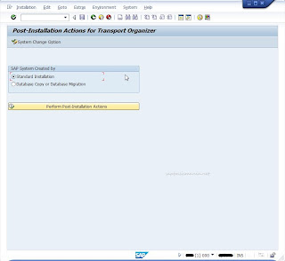 |
| Perform Post SAP Installation |
2. Since it's a fresh installation, choose YES to reinstall the CTS.
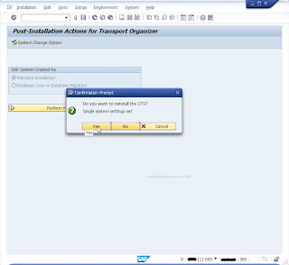 |
| Reinstall CTS |
3. If it's the first SAP installation you can configure it as SAP Transport Domain, otherwise include it in existing SAP Transport Domain.
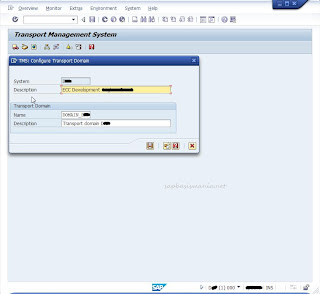 |
| Create SAP Transport Domain |
4. Enter the password for TMSADM user.
 |
| TMSADM and password |
5. Your SAP Transport Domain is now created.
 |
| New SAP Transport Domain is created |
6. Now you can add virtual system QA & PROD for your complete system landscape (you can replace it later when you've installed QA & PROD).
From initial screen STMS -> Overview -> Systems -> SAP Systems -> Create -> Virtual System.
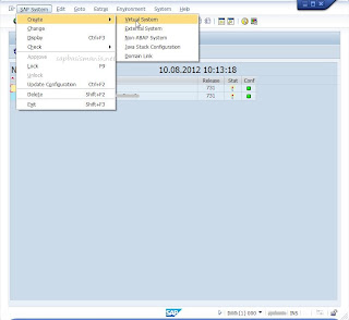 |
| Create SAP Virtual System |
7. Enter Description
 |
| Add QA Virtual System |
Repeat the above step for Virtual Production.
 |
| Add Prod Virtual System |
8. Now you begin to setup SAP Transport Route.
From initial screen STMS -> Overview -> Transport Route -> Configuration -> Standard Configuration -> Three Systems in Groups
From initial screen STMS -> Overview -> Transport Route -> Configuration -> Standard Configuration -> Three Systems in Groups
 |
| Setup Transport Route - Standard Configuration |
9. Enter your DEV, QA & PROD system respectively.
 |
| Enter the three System Group |
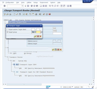
10. It's better to create Transport Target Group if you have multiple clients in your target system.
From Transport Group -> Edit -> Transport Target Group -> Create
From Transport Group -> Edit -> Transport Target Group -> Create
 |
| Create Transport Target Group |
11. Enter the name of Target Group and enter the target clients for both QA and PROD Target.
 |
| Target group name and target clients QA |
 |
| Target group name and target clients PROD |
12. Now from Edit -> Transport Route -> Create to create your transport route.
(You can choose in Graphical Mode or Hierarchical View).
Integration System : <DEV SID>
Target Group: <QA Target Group>.
(You can choose in Graphical Mode or Hierarchical View).
Integration System : <DEV SID>
Target Group: <QA Target Group>.
| Create The Transport Route |
13. Do the above steps for
Delivery Source: <QA SID - client>
Delivery Target: <PROD Target Group>
Delivery Source: <QA SID - client>
Delivery Target: <PROD Target Group>
 |
| Transport Route for target PROD |
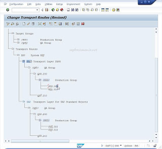
14. Now your SAP Transport Route is fully configured and shown like below
| Fully configured SAP Transport Route |
source(http://www.sapbasismania.net/)
Subscribe to:
Posts (Atom)


